Air Humidifier,Aroma Mist Humidifier,Homedics Humidifier,Room Humidifier GUANGDONG DEERMA TECHNOLOGY CO., LTD. , https://www.guangdongdeerma.com
Keywords: injection molding machine; V360; energy saving; frequency conversion;
INTRODUCTION The plastics industry has developed more and more rapidly in recent years, and the injection molding industry is also ushering in an opportunity for rapid development. At the same time, the competition within the industry is also becoming increasingly fierce. In addition to the emphasis on product quality and brand, manufacturers are also paying more attention to the control of production costs. It is known from the process of the injection molding machine that the cost of electric energy consumption accounts for a large proportion in the cost of injection molding products. Therefore, whether or not electric energy loss can be effectively reduced has attracted the attention of various injection molding machine manufacturers and users. With the promotion of variable frequency speed control technology, frequency conversion speed regulation has been widely used in the field of drive control and energy saving, especially in the case of pump load applications with variable frequency control and significant energy savings. This article takes four V360 series inverters as an example to introduce a frequency conversion control application program for the injection molding machine industry.
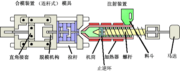
First, the process description Ordinary injection molding machine usually hydraulic transmission, the structure shown in Figure 1, mainly including the injection device, open and close mold device, hydraulic transmission device and electrical control device. 
Injection molding machine molding process is a process in accordance with a predetermined cycle, that is, to achieve a certain mold-locking - nozzle-advanced - plastic injection - pressure - cooling - pre-plastic - injection platform back-opening - removal of products and other processing processes to reach a certain Product molding.
The loss in the ordinary injection molding process mainly comes from the following points:
1, overflow loss. With different products and processing processes, the hydraulic pressure, flow rate, and pressure required for each process are different. So for the pump motor, the load in the injection molding machine injection molding process is in a state of change. The pump flow is designed according to the maximum flow rate required. When the pump is operating, the hydraulic flow is provided at a constant speed. When the flow rate required by the injection molding machine is less than the maximum flow rate, the excess hydraulic pressure will flow back through the overflow valve. Some of the energy is lost.
2, throttling loss. When the hydraulic oil flows through the orifice of the valve, there will be a certain pressure drop, which is the throttling loss. Due to the large throttle area of ​​the directional valve, most of the throttling losses occur on the proportional valve. At the same time, due to long-term hydraulic full-circulation flow and mechanical friction of hydraulic components, resulting in high oil temperature, excessive noise, mechanical life and other shortcomings.
3, design margin loss. Usually in the design, the commonality will be taken into account and the design is based on the maximum capacity. Therefore, the capacity of the user's oil pump motor design is much higher than the actual need, there is a phenomenon of “big horse-drawn carsâ€, resulting in a large amount of wasted electricity.
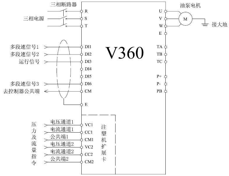
Second, the control program for injection molding machine molding process and process characteristics, designed a four-way V360 series inverter equipped with a dedicated expansion card program, the system structure shown in Figure 2, as follows:
1. The dedicated expansion card integrates four analog input channels, two voltage types, and two current types, providing input interfaces for different types of flow and pressure commands;
2, integrated multi-speed control, flow and pressure set signal can be superimposed after the given frequency converter operating frequency;
3, can set the bottom flow, improve the system's response speed and stability. 
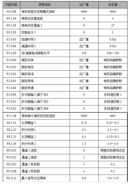
Third, the system wiring and main parameters set system wiring diagram shown in Figure 3: 
The main setting parameters 
It has a dedicated operating frequency given channel for injection molding machine, short acceleration and deceleration time, and rapid system response;
The system has a strong current suppression capability, effectively avoids the occurrence of faults such as overcurrent, and the system operates stably.
Multi-speed and flow, pressure command superimposed function to facilitate the realization of different processes on the operating frequency requirements;
The temperature rise of the hydraulic oil in the injection molding machine is significantly reduced, effectively extending the service life of the hydraulic oil.
System energy-saving effect is significant, generally up to 30% to 50%.
Concluding remarks This article describes a four-party V360 inverter-based injection molding machine drive program, the program has a stable supply pressure, to achieve the increase or decrease the number of input air compressor automation, energy-saving effect is remarkable, effectively extending the system of equipment life . It has been successfully applied to multiple air compressor linkage control systems.
references:
"V360 Series High-Performance Vector Inverter Manual" Shenzhen Sifang Electric Technology Co., Ltd. "Specification for Injection Molding Machine Expansion Card" Shenzhen Sifang Electric Technology Co., Ltd.
Abstract: This article describes the successful application of the Quartet V360 series inverter on the injection molding machine. Fourth, program advantages:
figure 1
figure 2
image 3