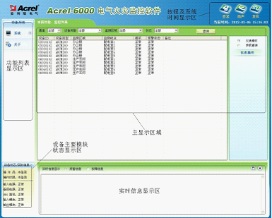
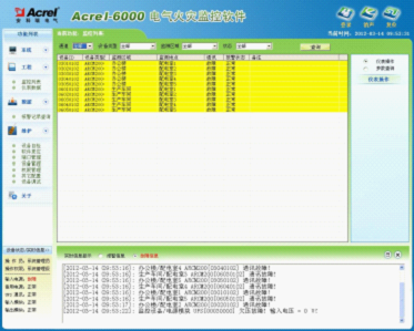
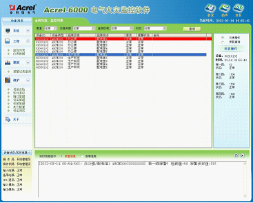
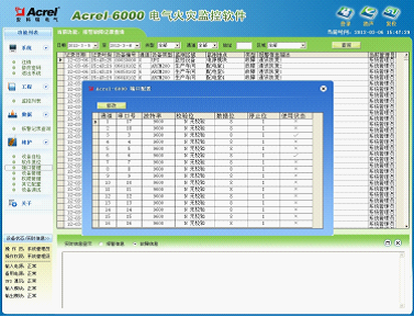
Ankerui  Qing Qing Jiangsu Ankerui Electric Appliance Manufacturing Co., Ltd. Jiangyin , Jiangsu 214405 Abstract The Ankerui residual current type electric fire monitoring system adopts the ARCM residual current type electric fire monitoring device and adopts on-site local networking method. After networking, it communicates via the field bus and transmits it to the background remotely to use it for shopping malls, hotels, etc. Low-voltage power distribution systems such as airports, banks, hospitals, and factories are used for electrical fire monitoring. This article through the introduction of the Huashan Hospital electrical fire monitoring system project, focusing on the structure of the Acrel-6000 electrical fire monitoring system, the equipment involved, the functions achieved and its significance. Key words: fire detector; electrical fire; Huashan Hospital; Acrel-6000; 0 Foreword The Baoshan Branch of Huashan Hospital affiliated to Fudan University (Renshan Hospital in Baoshan District) was a Grade II A comprehensive public hospital funded by the Baoshan District government in 2000 with a total investment of RMB 140 million. It is located at No. 1999 Changjiang West Road. The hospital covers an area of ​​25090 m2, a building area of ​​27406 m2 , a green area of ​​12,759 m2 , and a greening rate of 42.5%. It has approved 360 beds, 360 open beds and 604 employees. There are 9 senior high school students, 58 high school students, 107 intermediate students, and 17 master students. There are 14 administrative and party group departments, 23 clinical departments (11 primary divisions, 12 secondary divisions), 6 medical and technical departments, and 12 nursing units. For the third time in a row, it won the title of Shanghai Civilized Unit. In 2011, it was awarded a unit of employee satisfaction by the Shanghai Municipal Labor Relations. In 2010 and 2011, the leadership team of the hospital won the title of “Five Teams†in the Baoshan District Health System for two consecutive years. In 2013, he won the May 1st Labor Collective Certificate in Baoshan District. This project is the Huashan Hospital emergency building, hospital building, administrative building, medical technology building, and infection building fire monitoring system. The monitoring scope is mainly the low-voltage power distribution room in the basement and the power distribution cabinet in each floor. Acrel-6000 fire monitoring takes full advantage of the latest developments in modern electronic technology, computer technology, network technology, and fieldbus technology, and performs distributed data collection and centralized monitoring and management of the power distribution system. The secondary equipment of the distribution system is networked. Through the computer and the communication network, the field devices of the decentralized power distribution station are connected into an organic whole, and remote monitoring and centralized management of the power grid operation are realized. The system can effectively predict and monitor the leakage and leakage due to leakage , and can accurately monitor the fault and abnormal state of the electrical circuit. It can discover the fire hazards of the electrical fire and promptly remind the personnel to eliminate these hidden troubles. It helps enterprises to save labor costs and improve work efficiency. 1 System Requirements Analysis Detection of leakage current, over current, over temperature and other signals, sound and light signal alarm, accurately report the fault line address, monitor the changes in the point of failure. Store various fault and operation test signals to show system power status. 2 Reference standards The system complies with the People's Republic of China national standard GB14287.1-2005 "Electrical fire monitoring system Part 1: Electrical fire monitoring equipment." 3 system structure Acrel- 6 000 electrical fire monitoring system is a company independently researched and developed for receiving residual current type electrical fire detectors and other field equipment signals to realize the alarm, monitoring, control, and management of protected electrical circuits running on computers. Level hardware/software system. This system is applied to fire control centers in large shopping malls, living quarters, production bases, office buildings, shopping malls and hotels, and remotely measures, remotely adjusts, remotely controls, and remotely detects the detectors scattered in buildings to facilitate monitoring and management. The system uses a standard Modbus field bus to connect detectors with communication functions. When the detected parameters in the field protection circuit exceed the alarm setting value, it can send alarm signals, control signals, can indicate alarm locations and save alarms. information. The main equipment of Acrel- 6 000 /Q100 electrical fire monitoring system is as follows: l Computer: Industrial PC, C ore 2 2.66G/1G/320G+ keyboard and mouse 17 " LCD monitor, W indows XP , A crel-6000 electrical fire monitoring system software; l Input and output modules: Built-in ARTU remote intelligent I/O modules developed by the company; l sound and light alarm: built-in five-tone signal speaker, LED indicator, silence button; l Standby power: built-in 1 kVA on-line long-term UPS. l host panel components layout and function description 1: Alarm indicator (red), the indicator lights up when the system receives the monitoring alarm signal. 2: Fault indicator (yellow), the indicator lights up when the system receives a fault alarm signal. 3: Running indicator (green). The indicator is on when the system is operating normally. 4: Main power indicator (white). Lights when the main power supply is used. 5: Standby power indicator (white). Lights up when using standby power. 6: Mute button (black) to eliminate and restore the alarm sound. 7: Manually output button (black), manually start the control output of the protected circuit under alarm state. The distribution of this system mainly uses a computer distribution network structure. 1) Station control management Station management The management personnel of the electrical fire monitoring system are the direct windows of human-computer interaction and the top part of the system. Mainly by the system software and necessary hardware equipment, such as monitoring host, display, UPS power supply and other components. The monitoring system software calculates, analyzes, and processes various types of data on the site, and responds to the on-site operations by means of graphics, digital display, sound, and indicator lights. Monitoring host: used for data acquisition, processing and data forwarding. Provides data interfaces within or outside the system for system management, maintenance, and analysis. UPS: Ensure the normal power supply of the computer monitoring system. When the power supply problem occurs in the entire system, ensure the normal operation of the station control and management equipment. 2) Network communication layer Communication medium: The system mainly adopts shielded twisted pair, uses RS485 interface, MODBUS communication protocol to achieve real-time communication between the field device and the host computer. 3) Field device layer The field device layer is a data acquisition terminal, mainly ARCM100-Z, ARCM200 residual electrical fire monitoring detectors. Can monitor single-channel leakage current, each phase cable temperature signal, each channel has a broken line, short circuit detection function; standard 35mm rail mounting, LCD display; screen retention function, when the leakage fault occurs, the channel display screen temporarily stays, Indicates the value of leakage or over temperature in the channel to facilitate the fault recording of the host computer. With the event storage function, the alarm can record the time, type, and parameter of the alarm, can be recorded according to the alarm , and analyze the power consumption at the site to eliminate Faults are provided on the basis of field bus communication technology, PC management software can always monitor the operation of the scene, timely detection of alarm information. The standard MODBUS protocol can be connected to various standard systems; it has a high degree of integration, networking, a high degree of intelligence, and reasonable operating characteristics . The distributed I/O controller connected to the fieldbus forms a data acquisition terminal and uploads the collected data to the data center. The measuring instruments are responsible for the most basic data collection tasks. The data they monitor must be complete, accurate and transmitted to the monitoring host in real time. It is convenient for operating personnel to monitor the status of field equipment operation, fault alarms, etc. to effectively prevent the occurrence of fire accidents. 4 system function This set of PC software Acrel- 6 000 electrical fire system. Mainly has the following function characteristic: The friendly man-machine contact surface, may gather the scene equipment the surplus electric current data and the temperature in real time and the time regularly, and has the warning prompt sound and light alarm and so on the function. The customer can set the alarm temperature value and leakage current value according to actual needs. When the alarm fault is removed, it can be reset remotely. The system can record alarm events, dates, alarm values, over-line values, and generate reports. 1) System main interface After the system self-test is completed, you can enter the main interface of the system, as shown in the following figure: l The system main interface is mainly divided into five areas: "button and system time display area", "function list display area", "device main module status display area", "main display area" and "real-time information display area". l In the "button and system time display area", there are three operation buttons "login", "silencer", and "reset" and the system time display. l In the “function list display areaâ€, each function menu of the application program is displayed. The contents of the function menu are determined according to the current login operator's authority. l In the "Device Main Module Display Area", the status information of the current operator, input power supply, backup power supply, UPS communication, input module, and output module is displayed. When the main module of the device fails, the status information of the corresponding module will change from "normal" to "failure" and be displayed in red. l In the "main display area", different contents are displayed according to the function selected by the operator. l In the "Real-time information display area", display the fault and alarm information of the equipment. When there is a fault or an alarm occurs, the corresponding "fault information" and "alarm information" selection boxes will be displayed in red. The operator can maximize the display of faults and alarm messages as needed. After the fault and alarm are released, the system will automatically clear the fault and alarm information. At this time, the operator can turn off the real-time information display area as needed. When a new fault or alarm occurs, the real-time information display area will be displayed again. 2) fault information prompt When the monitoring device detects a device failure, the monitoring device will issue the following information: l The failure unit on the main screen of running monitoring displays a yellow background; l Operation monitoring The main interface displays real-time fault information. The information content includes: time, device location, device number, and fault information (the display interface is as shown in the figure below); l In the "Real-time information display area", "fault information" is displayed in red. l The yellow fault indicator of the monitoring device is on and a fault tone sounds. 2) alarm information and reset When the monitoring device detects an alarm, the monitoring device will issue the following information: l The alarm unit on the main screen of the operation monitor displays a red background; l Operation monitoring The main interface displays real-time alarm information. The information content includes: time, equipment location, equipment number, alarm information; l In the "Real-time information display area", "Alarm information" is displayed in red. l alarm control output terminal output alarm signal; l The red alarm indicator of the monitoring device is on and an alarm sounds. 3) Alarm record query By clicking "Alarm Log Query" under the [Data] menu, you can enter the alarm record (action information query) interface as shown in the figure below. The user can query the corresponding alarm or the record under the action type within any time period in the interface. The operation mode is to select the start date, end date, query type and click the query button. 4) Port Management This management function can only be operated by "system management level". After the “System Management Level†permission is registered in the system, you can enter the port management interface as shown in the figure below by clicking “Port Management†in the [Maintenance] menu. This interface can modify the corresponding communication port, communication speed and usage status of each channel. 5 Concluding remarks With the development of smart buildings and the widespread use of electricity, people have become more aware of security awareness. The installation of leakage current fire system in public buildings is an inevitable trend of intelligent construction. The electrical fire system is conducive to discovering hidden dangers and dealing with hidden dangers in time. It is of great significance to prevent fires from happening. references [1]. Ren Chengcheng, Zhou Zhong. Principles and Application Guide for Digital Meters for Electric Power Measurement [M]. Beijing. China Electric Power Press, 2007. 4 [2].Zhou Zhong. Application of Power Meters in Energy Metering of Large-scale Public Buildings [J]. Modern Building Electronics 2010. 6 Battle Drone
As a plastic moulding company and contract manufacturer, Timeplex Industrial Limited sits at the centre of the supply chain and has a duty and an opportunity to make a positive environmental impact on the plastics industry.
More services we offer:
Features of Mini Quadcopter Drone toy:
Packing : RC Drones With HD giftbox
Battle Drone,Small Battle Drone,Rc Pocket Drone,Battle Drones Toy Timeplex Industrial Limited , https://www.catimeplexhk.com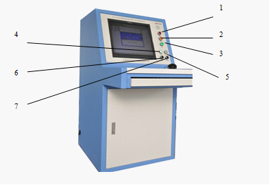


Besides of Metal Stamping Components,the Amplifiers metel chassises and Panels, we also complete solution for OEM/ODM Products & components, offer services of deep drawing services, EMI metal shielding parts, heat sink ,plastic molding products for custom, Plastic Injection Components, Metal Stamping Parts, home appliances accessories ,R/C drone and smart electronic toys etc.

1. 2.4G Long control distance and strong anti-interference.
2. 4.5CH: Ascending/Descending, left/right,Forward/Backward,Lean Left/Right
3. 5 lives for competing with LED lights
4. Different speed patterns to enjoy different flights.
5.Remote controller vibrates when drone gets heat in the racing.6.Packaging & Shipping
Shipping : Goods can be sent within 3-5 woking days after payment or deposit received
Shipping way : Sea shipment , Air shipment , Express shipment
Package List:
2 x Drone;
2 x Remote controller;
2 x battery(built-in);
1 x USB charger;
4 x Propeller;
1 x Manual;