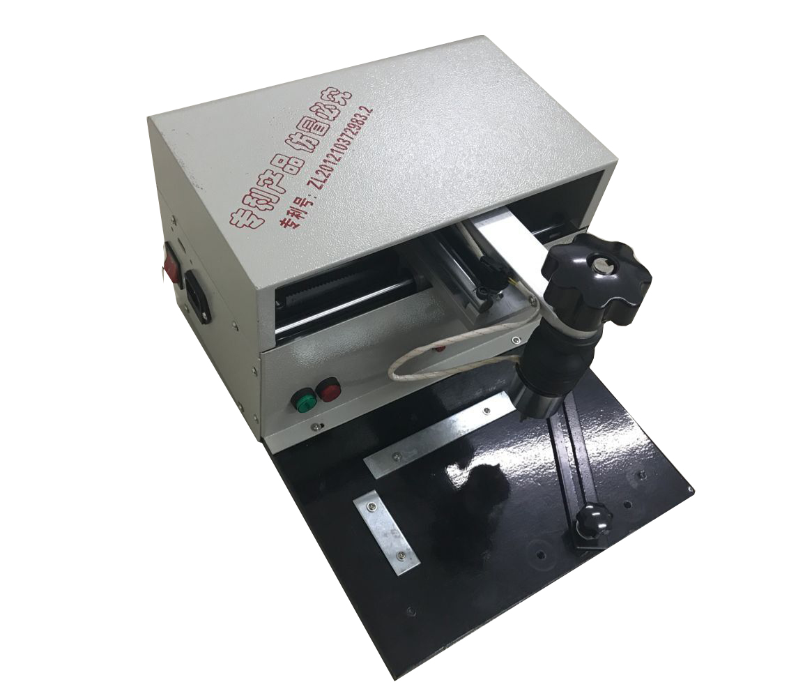
The principle of temperature monitoring system SO2 fan system consists of four parts: high-voltage motor, fluid coupling, speed increaser, SO2 fan. The monitoring of the system is mainly pressure and bearing temperature, bearing temperature measurement point. The XMB4226 is a new smart meter that performs data calculations with two relay outputs that display digital temperature values. 1, 2 end is the highest temperature relay output, 8 and 9 end are temperature high limit relay output, 5, 6, 7 end temperature measuring resistor, temperature measuring sensor adopts PT100 thermal resistance, 13 and 14 terminal power supply. The XMB4226 converts the detected resistance signal into a digital signal and displays it on the display. It compares this signal with the set axis temperature protection maximum and high limits. When the temperature exceeds the axis temperature protection high limit, the protection action. The equipment does not stop, only the alarm signal is issued; when the temperature exceeds the maximum limit of the shaft temperature protection, the protection action and the equipment stop. After the solution is checked, the temperature measurement system itself has no problem. Therefore, the focus is on the search of the on-site working conditions to see if there are any on-site working conditions that hinder the normal operation of the temperature measurement system. In addition, whether the temperature measurement system itself can be improved to adapt On-site working conditions. (1) The distance between the production site and the control room is about 400m. When the thermal resistance signal cable passes through the bridge, it is parallel with the power line, which may cause interference. Therefore, separate the signal cable from the power cable and the power supply in the control cabinet. The line is also separated from the signal cable to minimize interference sources. (2) The shielded wire of the original signal cable is connected to the grounding wire of the electrical part. The two share a grounding system. It is also possible to serialize the interference signal. Therefore, reinstall according to the electrical standard away from the electrical grounding system. A set of grounding is used as the ground for the signal cable. (3) Improvement of the temperature measurement system itself: Since the intervening interference signal is only instantaneous (not displayed on the computer), the existence time is very short, and it is possible to send the parking to the electrical system while satisfying the process conditions. The (or alarm) signal previously effectively removes the interference signal, which effectively eliminates false alarms and parking accidents caused by short-term signal interference. The specific measures are shown in Figure 3. In the XMB4226 smart meter maximum output terminals 1 and 2, the high limit output terminals 8 and 9 respectively install a delay output circuit, according to the field operating conditions, the maximum output terminal delay is 8s, the high limit output delay 4s. The maximum output delay is 8s as an example to illustrate the principle of operation: if the interference signal makes the 1 and 2 contacts close, the start time relay, the general interference signal will disappear in a few seconds, so the time relay within 8s is only activated. It can't move, the parking signal can't be sent out; if the shaft temperature reaches the maximum limit, the 1 and 2 contacts are closed, the start time relay, the normally open contact delay is 8s closed, the ZJ coil is charged, its normally open contact is closed, and the trip is turned on. Loop (tested, this delay process has no adverse effect on the fan body and operation). After the implementation of the above measures, the SO2 fan system is restarted after re-interlocking. After a period of operation, the instantaneous increase in temperature is significantly reduced, which basically eliminates the fan parking caused by the instantaneous increase of temperature, ensuring the SO2 fan system. normal operation. Dot peen marking works by electromechanically striking a carbide or diamond stylus assembly against the surface of a part to be marked.For example,dog tag engraver.The result is a succession of dots to create digits, text, logos, and 2D data matrix codes. Each such dot is the result of a pulsed current that runs through a solenoid, punches a magnet toward the surface, and subsequently returns the stylus to its starting position, awaiting the next pulse. Because each pulse occurs in only a fraction of a second, an entire 2D data matrix code, for example, can be completed in seconds (depending on the size).
Compressed air is not required.
Dot Peen Marking Machine,Pnematic Dot Peen Marking Machine,Pneumatic Marking Machine,Dot Markers,Dot Peen Marker,Dog Tag Engraver Wuhan HAE Technology Co., Ltd. , https://www.whinkjetcodingmachine.com
Notable Characteristics:
Cost effective
Requires no consumables
High speed accuracy
Will mark any material (including hardened steel)
